- This topic has 4 replies, 3 voices, and was last updated 3 years ago by
IremTorlak.
-
AuthorPosts
-
June 28, 2022 at 2:23 am #1996
Hi Angel, i have finished the printing of the THOR, also i have fabricate the single layer PCB, but i have a problem in the firmware, i have got the firmware for the single layer PCB from this link(http://thor.angel-lm.com/forums/topic/program-for-single-layer-pcb/) which you puplished before in the forum, am trying to run the first stepper motor for Art1, all connections and power good, the stepper and the drive also good, i have uplode the grbl to the arduino and tried to send move command through the IDE serial monitor for the motors specally Art1 first stepper but its not response to the control, the serial shows that the arduino successfully connected to the computer and Thor firmware, i have not connect any optical sensors ( homing sensors with P pinouts on the board) in the testing process, does the optical sensor was the problem?, can you send me the firmware again or help me to know what was the problem.
Thanks Alot
i am a mechatronics engineer and the robot is my final year project, which i will discuss it after one month afrom now, so i dont have much timeJuly 17, 2022 at 9:19 pm #2006Hi Mohamed!
Sorry, I have been busy these weeks and I just read your question.
I think that the problem could be related with the homing process. As you don’t have sensors to home the motors, GRBL doesn’t have a reference to start the motion. I think you can do a manual homing by placing the robot in the fully stretched upward position and sending the “Kill alarm lock” command ($X).
Here you have the documentation of GRBL commands in case you need it: https://github.com/gnea/grbl/blob/master/doc/markdown/commands.md
August 18, 2022 at 12:31 am #2034Hello Angel, Thanks for your reply, and sorry for my late reply.
I have done printing and assembling Thor, and the PCB works good.
I am working with my team on a control software using MATLAB-Simulink, allthing good but we need to know how you can calculate the Step per mm for each axis,
an how the stepper works depends on step per mm and in reality its moves rotationally( i thinks its about the grbl and how its works but can you explain), am experienced in 3D printing and know that the step per mm is for linear motion, so please help us in calculating the true value for each axis with no micro-stepping.and for the mechanical design of the robot, why did you choose these kind of printed gears in each axis, and how we can find the specifications of each.
and can you advise us with which kinds of heading we can focus in mechanical analysis and mechanisms chapter.
.
We are a group of mechatronics engineers and THOR is our Graduation Project, thanks a lot for helping us.
Mohammed.August 28, 2022 at 3:39 pm #2044Hi Mohamed! No need to apologize! You see I can’t answer immediately sometimes either.
The firmware I use to move Thor is a modified version of GRBL. And instead of using steps/mm what I did was to use steps/degree.
That is, the DEFAULT_X_STEPS_PER_MM variables of GRBL config files units are steps per rotation degree instead of steps per mm. And these are the values of the vars:#define DEFAULT_A_STEPS_PER_MM 44.5 #define DEFAULT_B_STEPS_PER_MM 270.0 #define DEFAULT_C_STEPS_PER_MM 270.0 #define DEFAULT_D_STEPS_PER_MM 265.0 #define DEFAULT_E_STEPS_PER_MM 20.0 #define DEFAULT_F_STEPS_PER_MM 250.0 #define DEFAULT_G_STEPS_PER_MM 250.0To calculate each one I just used the step angle of the stepper motor (usually 1.8 deg), the gear ratio of each articulation and the microstepping of the driver (usually 1/16).
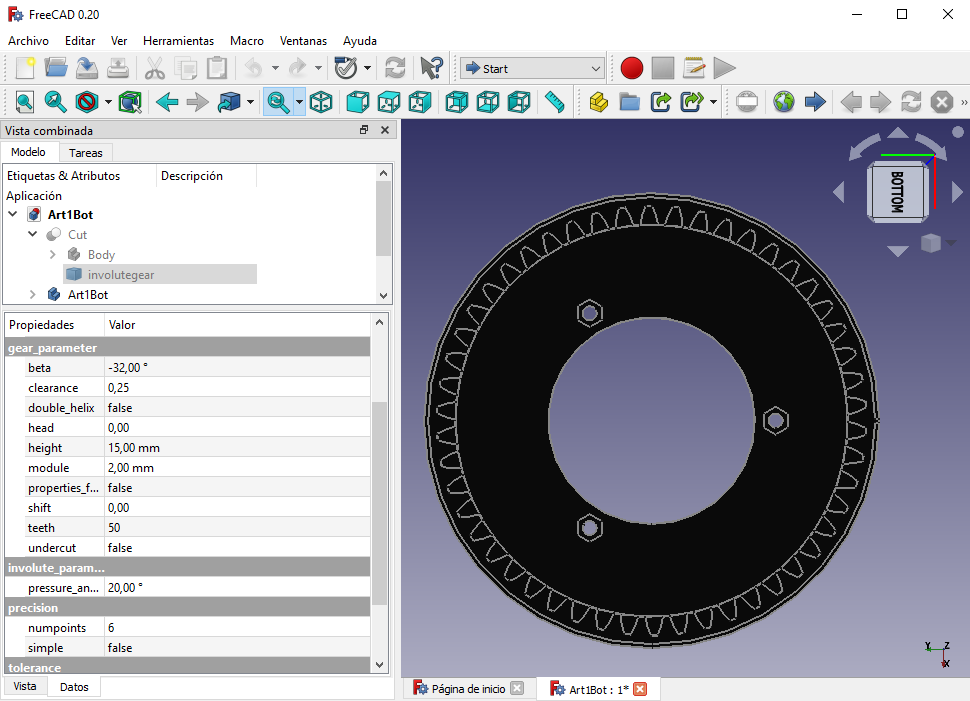
For example, for the first articulation, we have a stepper motor with 1.8 deg/step, a gear ratio of 5:1 (as the driver gear has 10 teeth and the driven one 50 teeth), and a microstepping of 1/16 configured in the stepper driver. So, (1/1.8)*16*5 = 44.4444… Rounding up to 44.5.About the printed gears, I used helical geard instead of spur gears because they have hreater tooth strength and can withstand higher loads. The parameter of each gear (module, angle, teeth, etc) can be seen in the FreeCAD model. If you open the FCStd file of a part with a gear, you can navigate through the Tree View to the involutegear object to see the parameters:
Hope this helps! 🙂
July 11, 2023 at 12:01 am #2203Hi Mohamed;
I wonder if you can share MATLAB studies related to the Thor robot arm with me. Thank you from now -
AuthorPosts
- You must be logged in to reply to this topic.