Firmware
This section will cover the steps to follow for the installation and configuration of the firmware, both for the Thor ControlPCB and the Fly Super8Pro board.
Thor ControlPCB
Installing Firmware
The installation of the firmware on the control board is pretty easy. To do it, we’ll use the Arduino IDE. Once you have it installed go to Downloads page and download the latest firmware files.
Unzip the downloaded file and navigate to grbl-1.0/grbl/examples/grblUpload. In this folder there is a file called grblUpload.ino that you have to open using Arduino IDE.
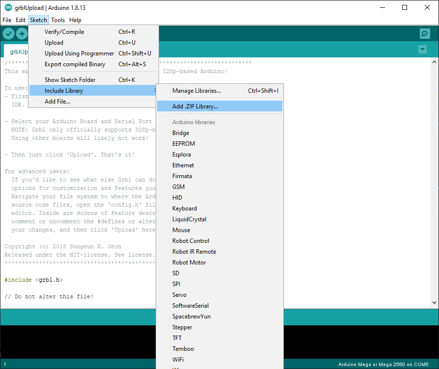
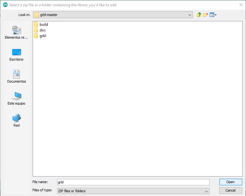
Click on Sketch > Include Library > Add .ZIP Library In the new window, navigate to the grbl-1.0/grbl folder and press “Open” to include it in the project (do not include the .zip file or the grbl-1.0 folder).
Connect the Arduino Mega to the PC without having the controlPCB attached to the Arduino.
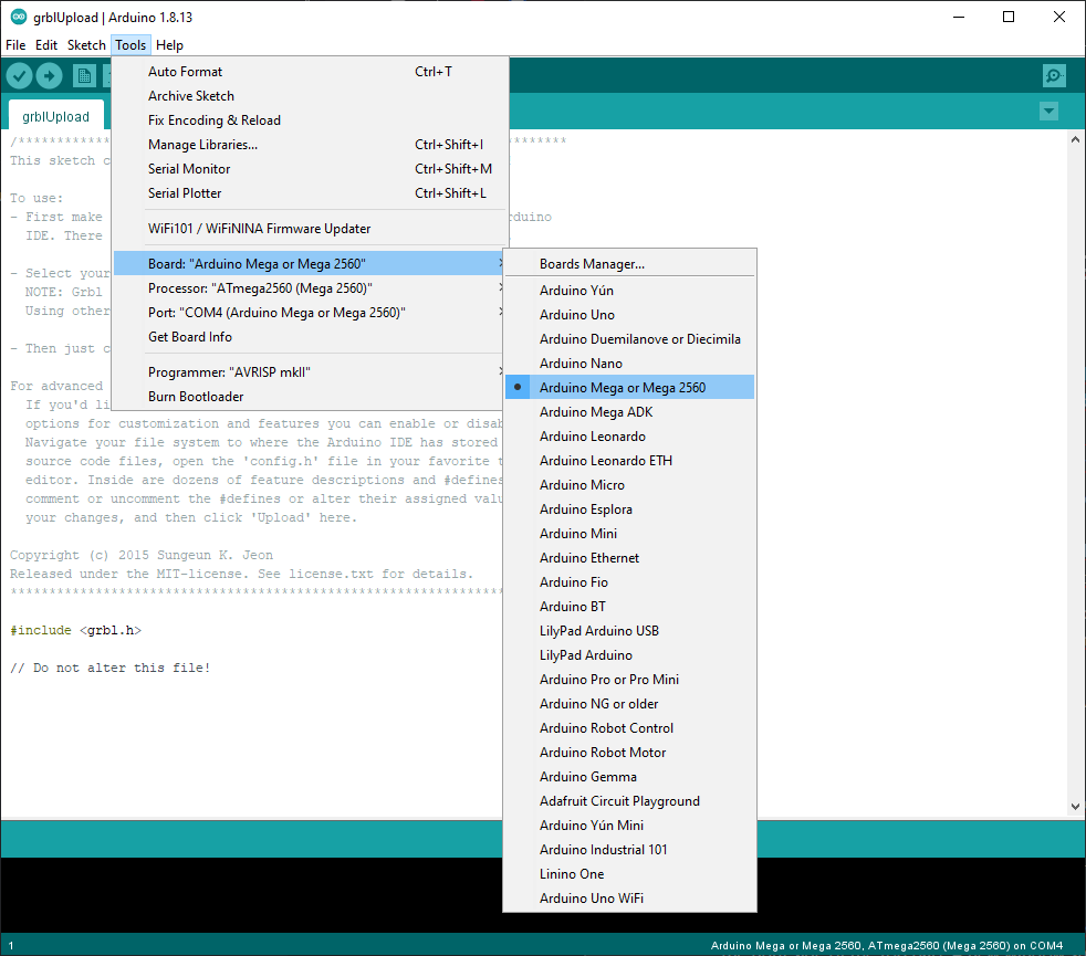
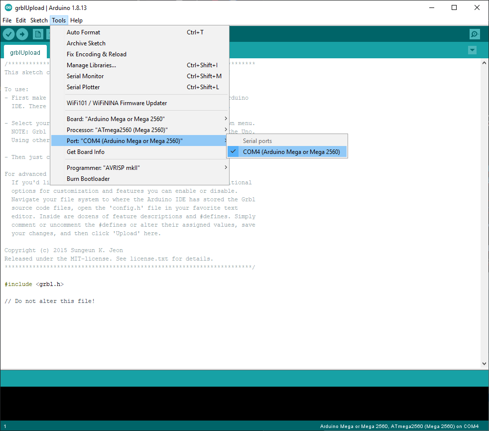
In the Arduino IDE, go to Tools > Board and select “Arduino Mega”. If it’s not automatically selected, go to Tools > Port and select the port where the board is connected.
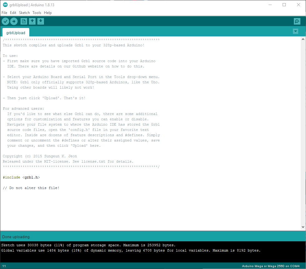
Press on the Upload Button (the one with an horizontal arrow) located on the topbar. After a few seconds the upload will finish and in the bottom bar the following message should appear: “Done uploading”.

Now you can attach the ControlPCB to the Arduino. and start with the configuration and testing.
Configuring Firmware
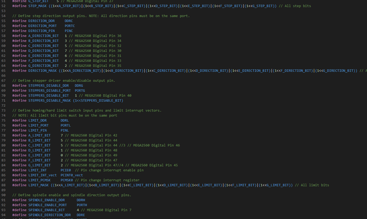
GBRL has a list of settings that can be configured. In order to make it work for Thor there are some changes that have to be made.
To do this configuration you can use the serial-console of your choice. In this guide we’ll use the one integrated in the Arduino IDE.
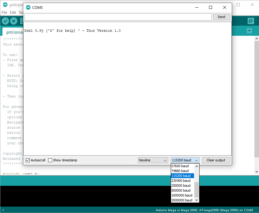
With the Arduino connected to the PC open the Arduino IDE and click the Serial Monitor button (in the right side of the top bar). A new window should appear.
Click on the baudrate selection box and select the 115200 option if it’s not already selected and select “Newline” option in the other selection box. Now you should see the following message in the console: “Grbl 0.9j [‘$’ for help] – Thor Version 1.0”
If you send the command $$ in the input text box and press enter the board will return the current GRBL configuration.
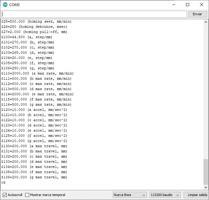
By default, the parameters should match with the following ones:
$0=10 (step pulse, usec)
$1=255 (step idle delay, msec)
$2=0 (step port invert mask:00000000)
$3=0 (dir port invert mask:00000000)
$4=0 (step enable invert, bool)
$5=1 (limit pins invert, bool)
$6=0 (probe pin invert, bool)
$10=3 (status report mask:00000011)
$11=0.010 (junction deviation, mm)
$12=0.002 (arc tolerance, mm)
$13=0 (report inches, bool)
$20=0 (soft limits, bool)
$21=0 (hard limits, bool)
$22=1 (homing cycle, bool)
$23=0 (homing dir invert mask:00000000)
$24=25.000 (homing feed, mm/min)
$25=500.000 (homing seek, mm/min)
$26=250 (homing debounce, msec)
$27=2.000 (homing pull-off, mm)
$100=44.500 (a, step/mm)
$101=270.000 (b, step/mm)
$102=270.000 (c, step/mm)
$103=265.000 (d, step/mm)
$104=20.000 (e, step/mm)
$105=250.000 (f, step/mm)
$106=250.000 (g, step/mm)
$110=2000.000 (a max rate, mm/min)
$111=800.000 (b max rate, mm/min)
$112=800.000 (c max rate, mm/min)
$113=800.000 (d max rate, mm/min)
$114=2000.000 (e max rate, mm/min)
$115=500.000 (f max rate, mm/min)
$116=500.000 (g max rate, mm/min)
$120=10.000 (a accel, mm/sec^2)
$121=10.000 (b accel, mm/sec^2)
$122=10.000 (c accel, mm/sec^2)
$123=10.000 (d accel, mm/sec^2)
$124=10.000 (e accel, mm/sec^2)
$125=10.000 (f accel, mm/sec^2)
$126=10.000 (g accel, mm/sec^2)
$130=200.000 (a max travel, mm)
$131=200.000 (b max travel, mm)
$132=200.000 (c max travel, mm)
$133=200.000 (d max travel, mm)
$134=200.000 (e max travel, mm)
$135=200.000 (f max travel, mm)
$136=200.000 (g max travel, mm)
In case they don’t match you can try to send the command $RST=$ . This command replaces the parameters values with the default ones (it’s handy if you are testing new parameters and you want to go back to the default ones).
You can also change the values one by one sending the command $parameter=value where “parameter” is the number of the parameter and “value” is the value of the parameter. For example, to set the step pulse time to 10 usecs we would send the command: $0=10
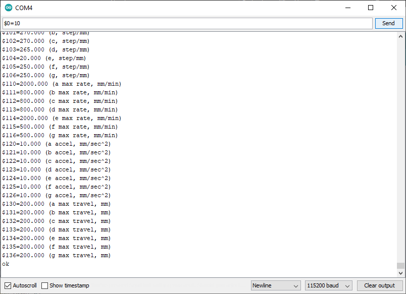
Change all not-matching settings and check that they are well changed by sending the $$ command and comparing them with the list above.
Note: All of these settings have been calculated for the original models of steppers, stepper drivers, belts, pulleys and gears. If you are using other components than the described in the BOM page, you may have to adjust them.
Testing Firmware
We will be using GRBL to control Thor motors. GBRL process GCode commands, so it would be a nice idea to know what are GCode commands.
These whould be the basic commands and how to use them:
Move : G0 & G1
Usage
G0 Annn Bnnn Cnnn Dnnn Xnnn Ynnn Znnn Fnnn G1 Annn Bnnn Cnnn Dnnn Xnnn Ynnn Znnn Fnnn
Variables
Not all variables need to be used, but at least one has to be used
- Annn : The angle to rotate to on the First Articulation (Motor #1)
- Bnnn : The angle to rotate to on the Second Articulation (Motor #2)
- Cnnn : The angle to rotate to on the Second Articulation (Motor #3)
- Dnnn : The angle to rotate to on the Third Articulation (Motor #4)
- Xnnn : The angle to rotate to on the Forth Articulation (Motor #5)
- Ynnn : The angle to rotate to on the Fifth & Sixth Articulation (Motor #6)
- Znnn : The angle to rotate to on the Fifth & Sixth Articulation (Motor #7)
- Fnnn : The feedrate per minute of the move between the starting angle and ending angle (if supplied)
Note: B&C must be the same number
Examples:
G0 A10 B45 C45 D-45 X15 Y5 Z-5 This code will move to 10º the 1st Art., to 45º the 2nd Art., to -45º the 3rd Art., to 15º the 4th Art. and will rotate the wrist (5th&6th Art)
G1 A20 X-20 F1000 This code will move to 20º the 1st Art. and to -20º the 4th Art at 1000 degrees/min speed
Tool : M3
Usage
M3 Snnn
Variables
- Snnn : Output tool signal value
Examples:
M3 S900 This command will move a servomotor connected to the ControlPCB STOOL pin to the opened position.
Testing GCodes
To finally test your motors follow the next steps:
- Connect the ControlPCB to the Arduino.
- Connect at least one stepper motor to the Control PCB
- Connect the 12-24V Power supply to the ControlPCB
- Connect the Arduino to the PC
- Open the Arduino IDE serial terminal and send a GCode command
If everything is fine you should be able to test you motors these way.
Help! It doesn’t work!
If during testings you don’t manage to move the motors, it could be either a firmware or electronics failure. Take a look at this list of possible errors and solutions:
- Check that you have connection with the Arduino and it has the firmware flashed: Open the console, select the proper Baud Rate and verify that you can read the Welcome message from GRBL: “Grbl 0.9j [‘$’ for help]”
- Check the wiring, may be the motor is not well connected or you are trying to move a different motor.
- Check the electronics: It’s possible that mistakes were made during the soldering of the ControlPCB. Using a multimeter, check all the soldering points to make sure that there are no short circuits or poorly soldered tracks.
- Check the stepper driver: Some stepper drivers have a small potentiometer in the upper face that controls the current that flows to the stepper motor. If this potentiometer is turned all the way off, the motor will not receive enough current to move. Check this video to know how to tune the driver’s potentiometer. Another common failure is driver burnout. You can replace the driver with a new one in case this is the case.
- If after checking all the above points you still can’t find the fault, don’t hesitate to ask in the forum providing as many details as possible so that the community can help you as best as possible.
Fly Super8Pro
Installing Firmware & Configuration
Installing the firmware on this board couldn’t be easier, let’s see it step by step as follows:
- Connect the micro SD card to the PC
- Download RepRapFirmware version 3.5.4 from the TeamGloomy repository
- Copy the firmware_super8pro_h723.bin file to the root of the SD card
- Go to the Downloads page and download the latest Fly Super8Pro configuration files
- Unzip the ZIP file you just downloaded
- Copy move the sys folder to the root of the SD card as well
- Connect the SD card to the powered off Fly Super8Pro board
- Connect the Fly Super8Pro board to your PC using the USB cable
- Done! The installation should be completed successfully
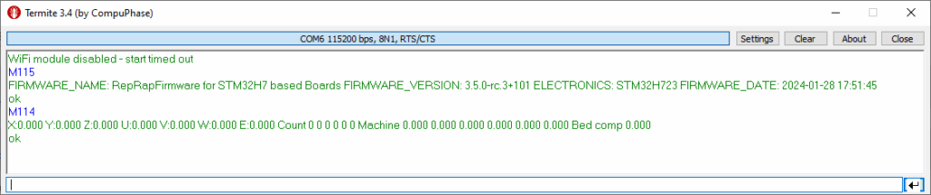
To test the board you can connect via serial using Termite, Arduino IDE or any other program that allows you to open a serial console with baudrate 115200.
Once you have established the connection to the board you can send GCODE commands and the board should return a message as a response.
With the M115 command you can see the installed firmware version.
With the M114 command you can see the current position of the motors. If the response to the M114 command does not contain the data for X, Y, Z, U, V and W it means that the configuration has not been performed correctly and you will have to perform again all the steps from the step 4.
If you have had any problem during the firmware installation, I recommend you to watch this video from 3D Mellow where they explain step by step the firmware installation process. Although the configuration is different from the one we use for Thor, it may help you to solve some doubts.
The Gcodes used in GRBL and RRF are similar, but not all of them are the same. I recommend you to visit the Duet3D page to familiarize yourself with the GCODES used in RRF.
Configuration tweaks
If you have used the recommended stepper motors and drivers, you do not have to make any additional adjustments.
If you have used a driver with a microstepping other than 1/16, motors with less steps/rev or motors with a gearbox other than the one indicated in the BOM, you will have to adjust the config.g file.
This file is properly commented so that you can easily find the parameters you need to modify.