Hi Mohamed! No need to apologize! You see I can’t answer immediately sometimes either.
The firmware I use to move Thor is a modified version of GRBL. And instead of using steps/mm what I did was to use steps/degree.
That is, the DEFAULT_X_STEPS_PER_MM variables of GRBL config files units are steps per rotation degree instead of steps per mm. And these are the values of the vars:
  #define DEFAULT_A_STEPS_PER_MM 44.5
  #define DEFAULT_B_STEPS_PER_MM 270.0
  #define DEFAULT_C_STEPS_PER_MM 270.0
  #define DEFAULT_D_STEPS_PER_MM 265.0
  #define DEFAULT_E_STEPS_PER_MM 20.0
  #define DEFAULT_F_STEPS_PER_MM 250.0
  #define DEFAULT_G_STEPS_PER_MM 250.0
To calculate each one I just used the step angle of the stepper motor (usually 1.8 deg), the gear ratio of each articulation and the microstepping of the driver (usually 1/16).
For example, for the first articulation, we have a stepper motor with 1.8 deg/step, a gear ratio of 5:1 (as the driver gear has 10 teeth and the driven one 50 teeth), and a microstepping of 1/16 configured in the stepper driver. So, (1/1.8)*16*5 = 44.4444… Rounding up to 44.5.
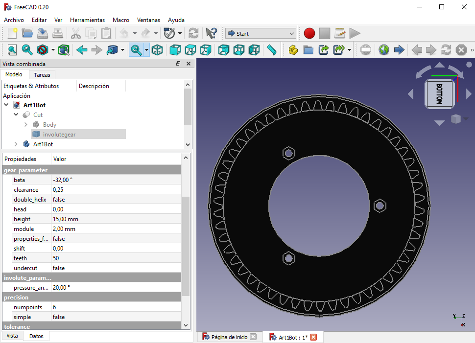
About the printed gears, I used helical geard instead of spur gears because they have hreater tooth strength and can withstand higher loads. The parameter of each gear (module, angle, teeth, etc) can be seen in the FreeCAD model. If you open the FCStd file of a part with a gear, you can navigate through the Tree View to the involutegear object to see the parameters:
Hope this helps! 🙂